Our research target is to build a method to create an image-based computational model of the mitral valve based on medical images.
It includes:
– Porcine mitral valve image acquisition
– Image processing to automatically extract the anatomy
– Fast Mitral Valve Simulation, biomechanical modeling to reproduce the mitral valve behavior while closing
– Fluid-Structure Interaction in order to model complex behavior such as leaks (current work)
Porcine mitral valve image acquisition
Our models are extracted from porcine hearts imaged using micro-Computed Tomography (μCT) scan in the Harvard Center for Nanoscale Systems. Acquisitions have been done in 2017, 2018 and 2019.
For each subject, two states are acquired: one with no pressure to have an unstressed valve state and one with 120 mmHg of air pressure delivered through the aorta to close the mitral valve and statically load it.
Our protocol is established to ensure high quality μCT scans and included carefully supporting the heart and pressurizing with air:
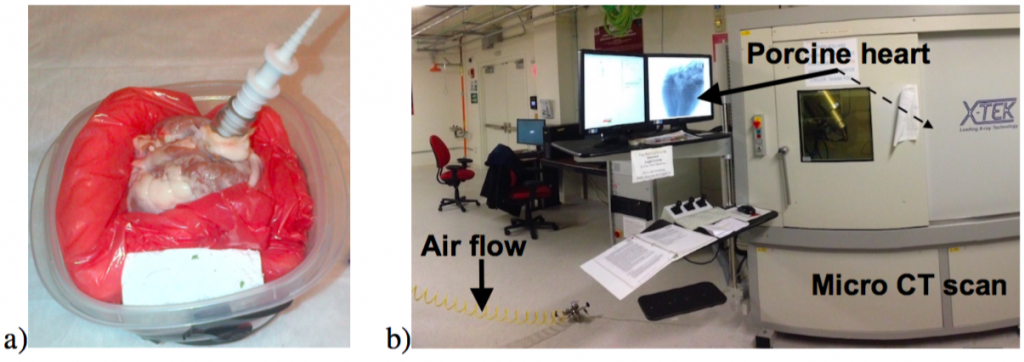 Figure 1. a) Foam system to support the heart. b) μCT scanner containing a heart pressurized using a regulated air supply.

Scanner settings:
- 1600 scanning angles
- 500ms exposure time
- X-ray tube power is set to 10.5W with U=175kV
- 0.5mm copper filter is used to achieve sufficient contrast
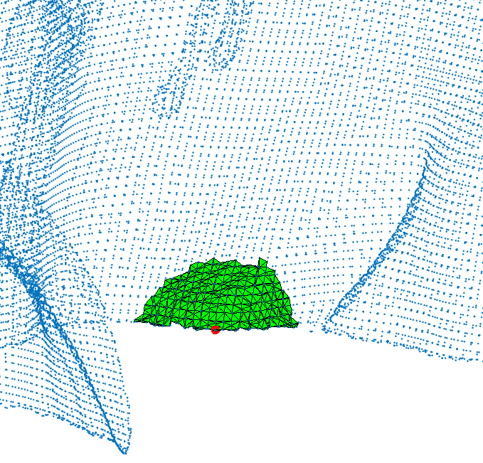
Figure 2: microCT scan images before 3D reconstruction
Results after reconstruction:
- 2000 x 2000 x 2000 voxel 3D image
- 0.1 mm isotropic voxel resolution
- 8-bit integer format
A region of interest for the mitral valve is selected.
These scans produced high contrast volumetric image.
Image processing to automatically extract the anatomy
Two components need to be extracted:
- The chordae
- The leaflets
The chordae
Valve chordae are generalized cylinders:
- central axis is a continuous curve
- radius varies along the axis
- sections are flattened ellipses
- classical model-based methods fail
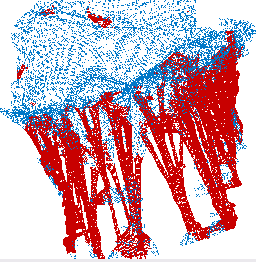
→ We proposed a topology-based method for chord extraction based on the number of connected components in a point neighborhood:
 |  |  |
| 1 connected component | 2 connected components | 3 connected components |
Example on three CT scans:
 | 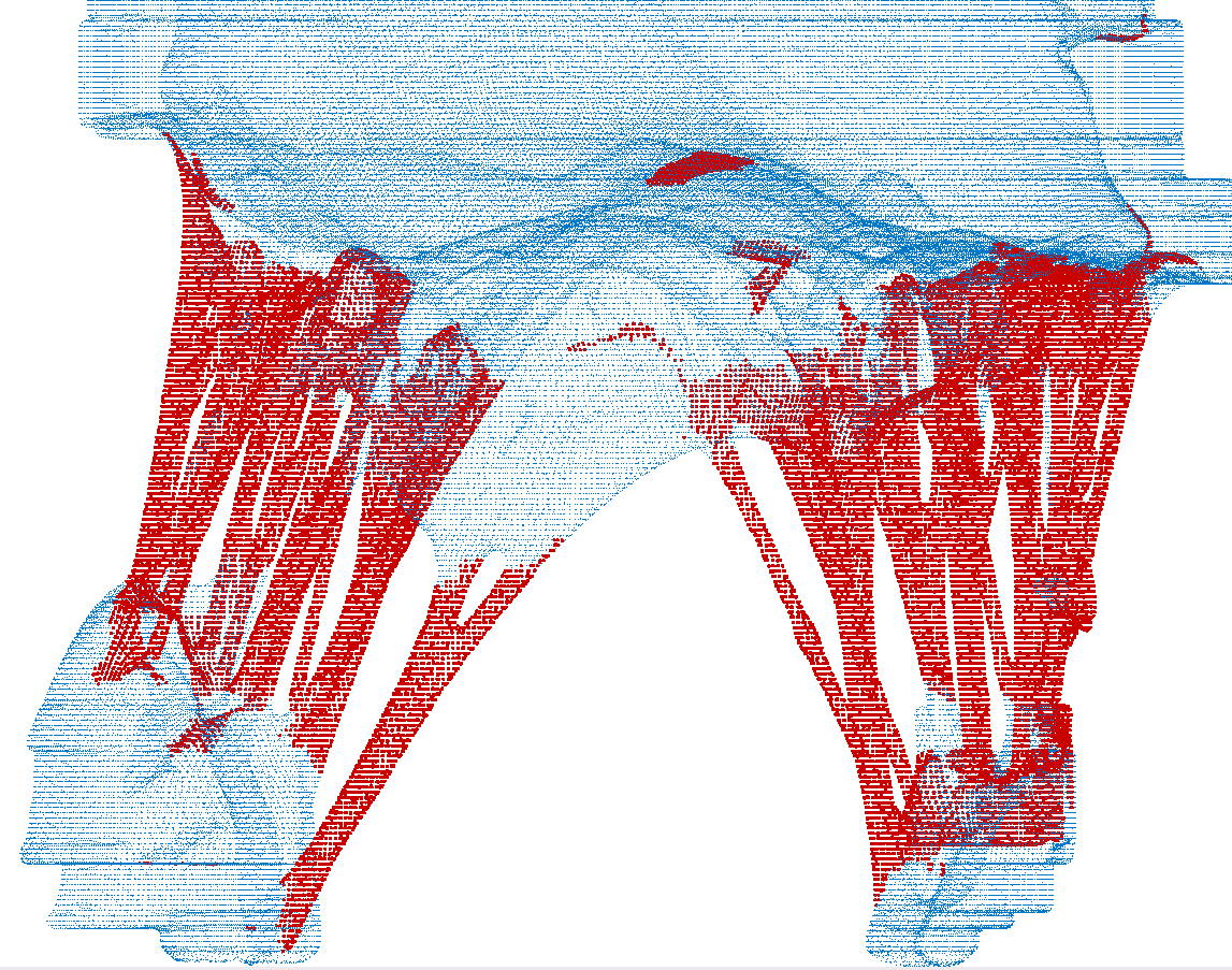 |  |
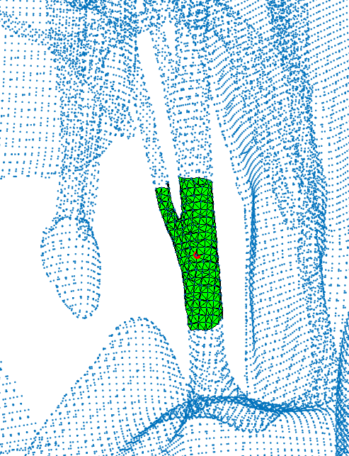
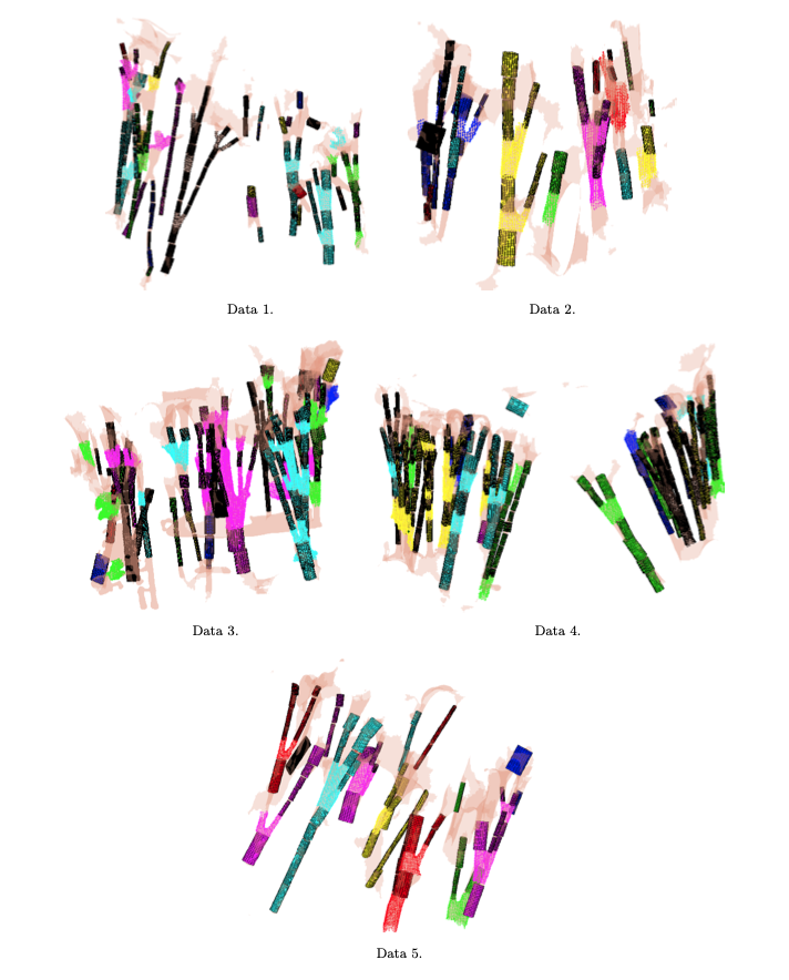
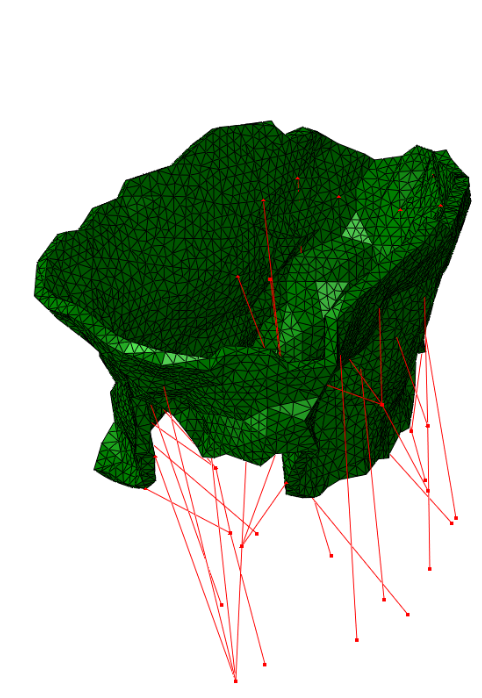
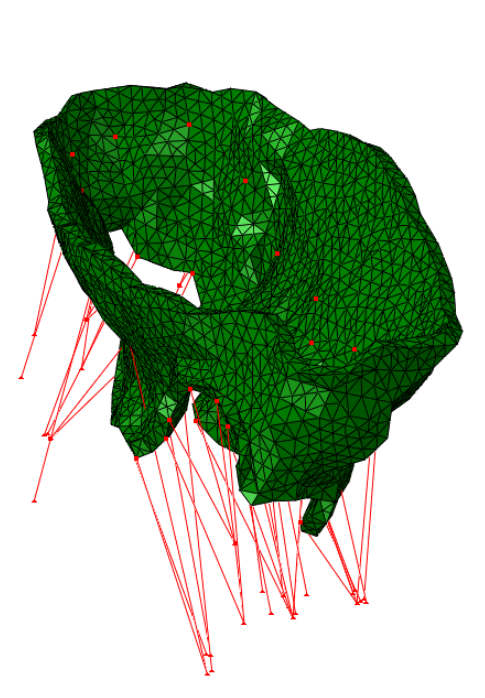
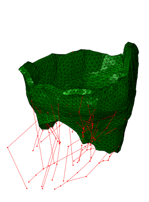
→ We proposed chordae tracking based on a local model-fitting approach. The chordae are represented in a form of trees of line segments. Example on five CT scans:
→ We proposed an optimization approach for correction of possible anatomical and mechanical inconsistency in the chordal trees. In this procedure, prior knowledge is considered and coupled with image data in order to obtain a more reliable input for further biomechanical simulation. Example on one CT scan:
Fast Mitral Valve Simulation
Mitral valve closure simulation done using SOFA framework.
Each node of the graph corresponds to a structure of the valve: the annulus, the leaflets, and the chordae.
Figure 3: SOFA scene graph of the mitral valve closure simulation . Grey: geometrical nodes, White: Linear solver, Green Integration scheme, Purple: Forces, Orange: Constraints and Blue: Degrees of freedom of the body.
Simulation parameters:
- An implicit Euler method is used for numerical integration → simulation remain stable
- 0.001 s time step → simulation to remain interactive
- Velocity damping: damping Rayleigh mass of 0.1 + Rayleigh stiffness of 0.5 → improve the convergence
Boundary conditions:
- Leaflets
- modeled as surface of constant strain triangles with linear elastic material model and constant thickness of 1 mm
- Corotational approach → supports large displacements
- Poisson’s ratio = 0.45 → model nearly incompressible tissue
- Self-collision monitored by penalty force
- Vertices near the annulus are pinned → allow only rotation.
- Pressure of 120 mmHg → peak systolic blood pressure
- Annulus
- Spring forces are applied such that the annulus is pulled from its initial configuration toward its final shape at peak systole.
- Direction and intensity of forces given by positions of closest points on the final state of the annulus
- Displacements given by the iterative closest point method
- Chordae
- Defined by a stiff mass-spring system
- Material modeled by an elastic law with parameters taken from the literature
- Points attached to the leaflet → behavior determined by that of the associated leaflet vertex
- Points attached to the papillary muscle → zero-displacement Dirichlet condition
- Others points → motion defined by the mass-spring behavior of the chordae.
Fluid-Structure Interaction in order to model complex behavior such as leaks
We study an FSI model based on the immersed boundary method that improves the detection of blood leakage.
FSI simulation setup:

Generic geometry
The method is demonstrated in three typical clinical situations:
- Mitral valve with leakage, when chordae are missing at the coaptation zone
- Mitral valve with bulging, when the two primary chordae are missing on the anterior leaflet
- An healthy valve with absolutely no orifice holes
 |  |  |
| Leakage | Bulging | Healthy |
Patient based geometry
The method has been tested on four valves extracted from real clinical data:
 |  |  |  |
| Real data #1 | Real data #2 | Real data #3 | Real data #4 |
Simulation result on real data #1: